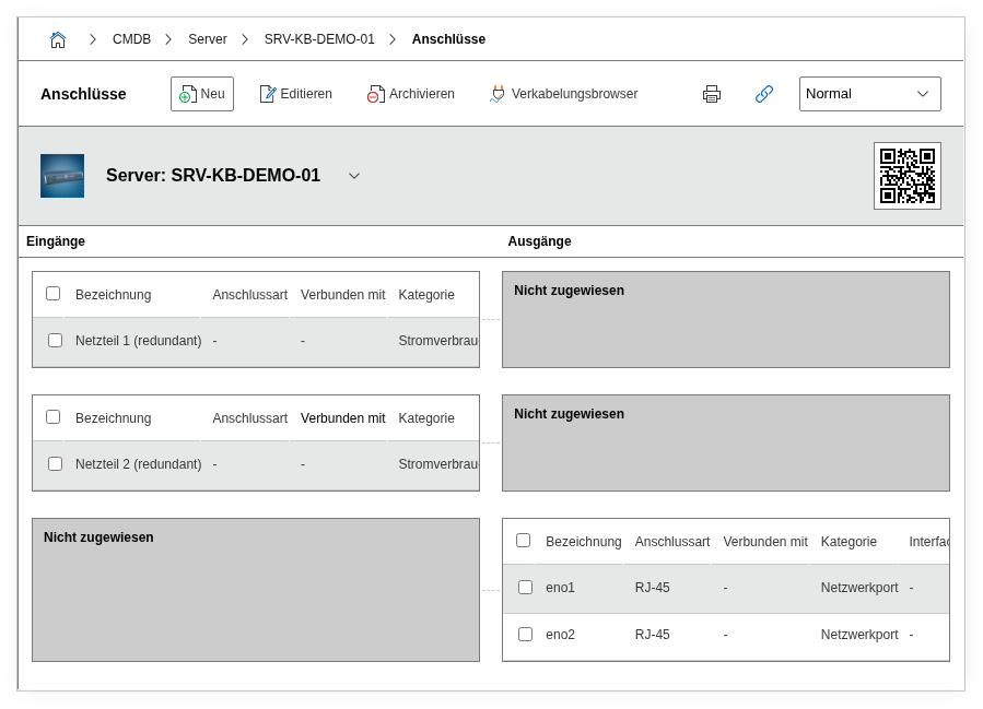
Category: Connector#
The Connector category documents the physical connectors of an object and their connections to other objects. It is a multi-value category -- any number of entries can be created per object, e.g. for a patch panel with 24 ports, a switch with dozens of network connectors, or a PDU with multiple power outputs.
Connectors are the physical endpoints of cables and, together with the cable object and the Port and Power consumer categories, form the complete cabling documentation in i-doit. Every network connection and every power supply has two ends -- and each end is a connector. Without this category, cable objects remain unlinked and the cabling view shows only fragments instead of continuous cable paths.
Understanding input/output correctly
The distinction between input and output is particularly relevant for power cabling: the power supply of a server is an input (it receives power), the output socket on the PDU is an output (it delivers power). For network connections, the logic follows the data flow. Consistent input/output maintenance ensures that the cabling view displays the direction correctly and that reports on power distribution deliver valid results.
Usage#
Typical use cases:
- Cabling documentation: Record every physical connector of a device and connect it to the counterpart at the other end of the cable. This creates a seamless, end-to-end cabling documentation from server to patch panel and on to the switch. The connector is the link between the specific device and the abstract cable object.
- Patch panel management: Create an entry for each patch panel port with title, interface type, and connection type. The associated connector on the counterpart can be directly linked via the object browser. A fully documented patch panel with 24 connectors shows at a glance which ports are occupied, which are free, and which are defective.
- Power connectors: Document the power supply via PDU connectors with plug type (e.g. C14, C13) and connection type (power cable). With redundant power supply, each power supply unit is mapped as its own connector. In combination with the Power consumer category, the complete power topology from the feed point to the end device emerges.
- Data center moves: During a hardware move between racks or locations, the Connector category shows exactly which cables need to be disconnected and reconnected at the new location. This significantly reduces the error rate during re-patching and shortens downtime.
- Cable trace: During network problems or power outages, the Connector category allows immediate tracing of which cable leads to which port -- including the cable object with length, type, and route. i-doit can visualize the entire cable path across multiple patch panels, provided all connectors are correctly linked.
Fields#
Title#
The name of the connector, e.g. PSU-1 Power, eth0 Uplink, or Port 12. This value appears in the list view of the category and is displayed as a label in the cabling view. Consistent naming greatly facilitates assignment during troubleshooting.
Input/Output#
Specifies whether the connector functions as an input or output. For network devices, the port on the switch is typically an input, on the server an output. For power distributors, the PDU input is the incoming power cable, the individual outputs supply the connected devices.
Interface#
The physical interface type of the connector, e.g. RJ-45, C14, C13, LC Duplex, SC Simplex, or USB-C. Dialog+ field -- custom values can be added as needed. This information is particularly helpful when planning new cabling, as it is immediately apparent which plug type is required.
Connection type#
Describes the type of cable or connection, e.g. Patch cable Cat6a, Power cable, Fiber OM4, or DAC cable. Dialog+ field -- new connection types can be added at any time. Together with the interface, a complete picture of the physical connection emerges.
Connected connector#
The connector on the counterpart to which this connector is connected. The target object and its specific connector are selected via the object browser. For example, if Port 12 of a patch panel is connected to Port Gi0/12 of a switch, this link appears bidirectionally in both objects.
Cable connection#
The cable object that establishes the physical connection between the two connectors. i-doit creates the cable object automatically when creating a connection, but it can also be created manually in advance and assigned. The cable object itself can carry additional attributes such as length, fibers, or routing.
Color / Wavelength#
For fiber optic connections, the colors or wavelengths used can be selected here. Multi-select field -- relevant in multiplexing scenarios where multiple wavelengths are carried over a single fiber.
Cabling system#
Links the connector with a parent cabling system object. This allows structured cabling (e.g. a building backbone or floor cabling) to be grouped and visually displayed as belonging together.
Description#
Free text for additional details: patch plan references, installation date, cable routing notes, VLAN assignment, or other specifics of the connection.
Internal fields
The category contains additional internal fields that are automatically managed by i-doit and typically do not need to be manually edited: Assigned input/output (connector_sibling) links the input and output sides of the same connector, Relation direction (relation_direction) controls the direction of the created relation, Assigned category (assigned_category) references the source category (e.g. Network port), and Used fiber/lead RX/TX (used_fiber_lead_rx, used_fiber_lead_tx) hold the specific fibers for fiber optic connections.
Technical reference#
| Property | Value |
|---|---|
| Category constant | C__CATG__CONNECTOR |
| Type | Global category |
| Multi-value | Yes |
| Assigned to | Server, Client, Switch, Patch panel, PDU, Monitor, etc. |
Fields (API reference)#
| Field | API key | Type |
|---|---|---|
| Title | title | Text |
| Input/Output | type | Dialog (selection) |
| Interface | interface | Dialog+ (extensible selection) |
| Connection type | connection_type | Dialog+ (extensible selection) |
| Connected connector | assigned_connector | Object browser (link) |
| Cable connection | cable_connection | Object browser (link) |
| Color / Wavelength | fiber_wave_lengths | Multi-select |
| Cabling system | wiring_system | Object browser (link) |
| Description | description | Text field (multi-line) |
API examples#
Create entry#
1 2 3 4 5 6 7 8 9 10 11 12 13 14 15 16 17 | |
Read entries#
1 2 3 4 5 6 7 8 9 10 | |
Update entry#
1 2 3 4 5 6 7 8 9 10 11 12 13 14 15 16 17 18 | |