Cable patches and paths#
With an extensive IT documentation, sooner or later, you will have to deal with the question of how to map the cabling. This article offers an introduction and describes how to wire hardware objects to each other.
Concept#
The mapping of cablings in i-doit is as versatile as in reality: Ethernet, fiberglass, electricity supply, connection of peripheral equipment - everything that has a connector and can be connected with a cable finds its place in the IT documentation.
i-doitvides a strict separation between the documentation of connections and the physical wiring. A good example is the network wiring via Ethernet. For one thing, the connections between active network components (switches, routers, firewalls) can be recorded in the category Network → Port. By this means, you can recognize which switch is connected with which server. Connection routes between several components become visible. On the other hand, passive components often play an important role: Patch panels and network outlets help to get things in line to avoid tangled cables. However, when the connections between active components cover your needs, you can ignore the passive components and their corresponding cables. i-doit is able to carry out the documentation of the cabling in the background; the user does not have to take out additional steps. If detailed knowledge of the cabling becomes necessary at a later time, the present documentation can just be complemented and the user does not have to start from scratch.
As usual in i-doit, the documentation of the cabling is executed with the help of objects and attributes. Beside numerous forms, i-doit supplies functions for visualization, evaluation and import. The following text describes these functions.
Category Folder for Cabling#
Every object type can be configured with the category folder Cabling. By this means, objects of these selected types receive the categories Connectors and Interface.
The category folder does not only serve as a superordinate level for the specified subcategories, but also offers some interesting visualization options for the cabling:
| Tab | Description |
|---|---|
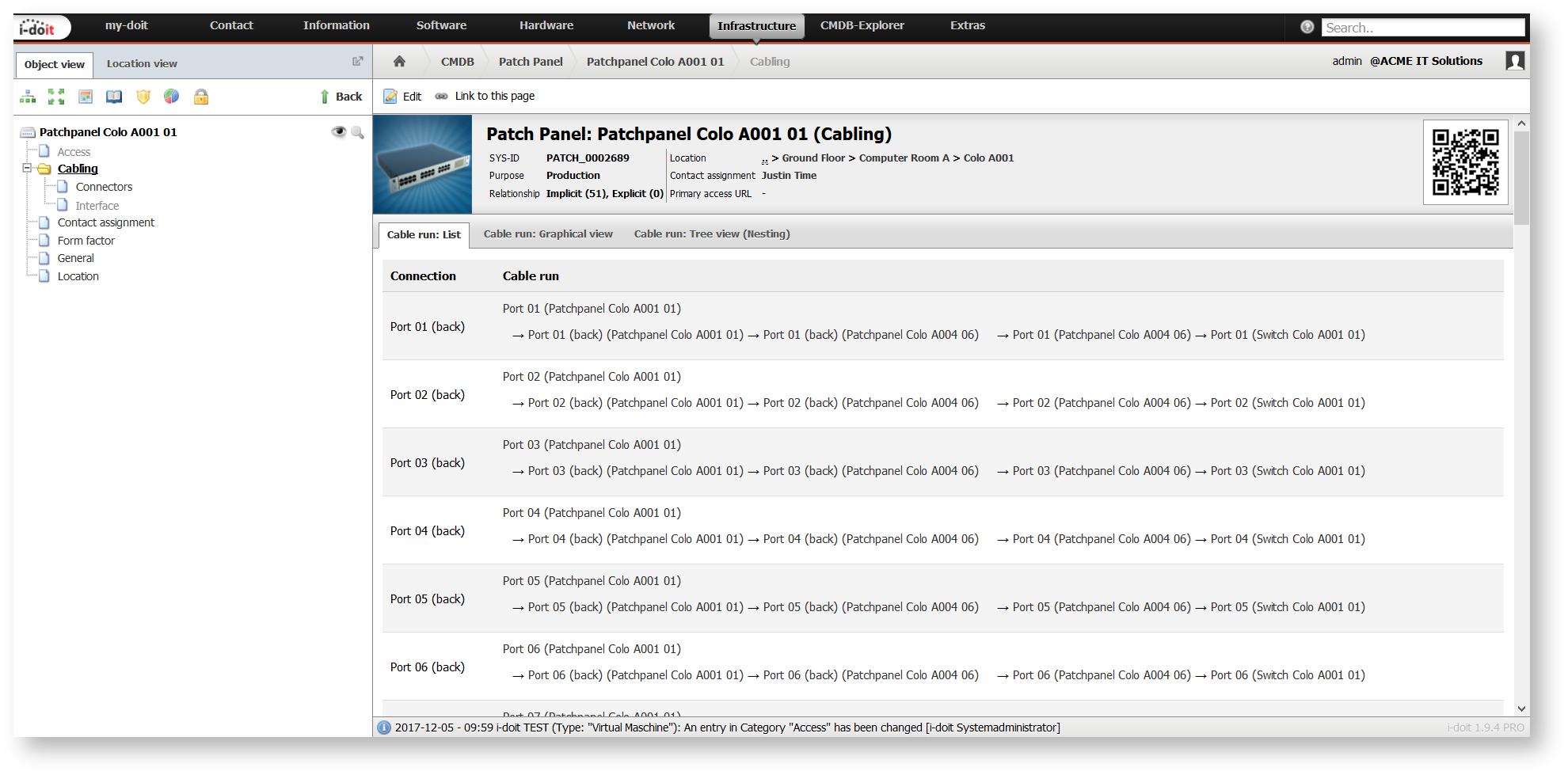
| Cable run: List | Every connection (see Connectors category) with a complete cable route is listed. |
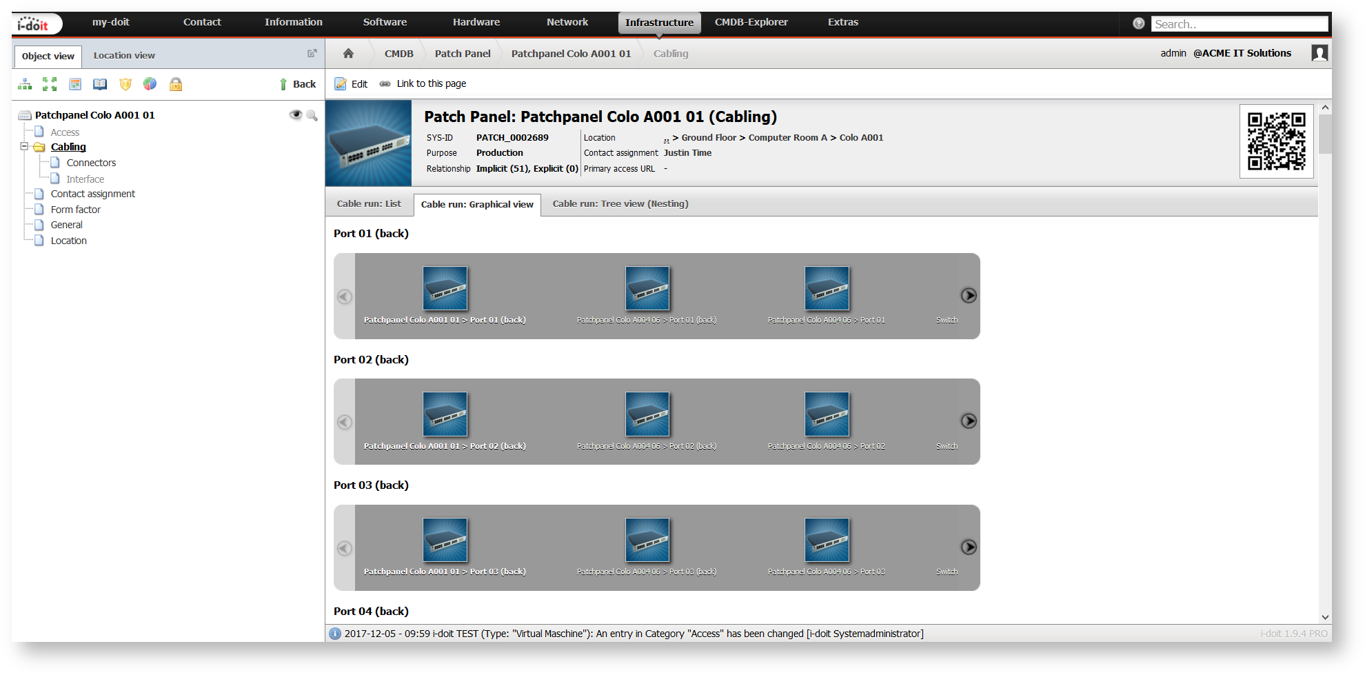
| *Cable run*: Graphical view | In contrast to the above mentioned list view, all objects are additionally shown with pictures. |
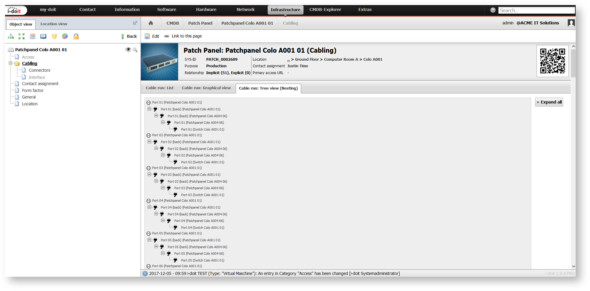
| *Cable run*: Tree view (Nesting) | The cable route is displayed as a tree structure for each connector. |
The category folder is suited for all objects which contribute an active or passive part to the cabling.
Category Folder for Connectors#
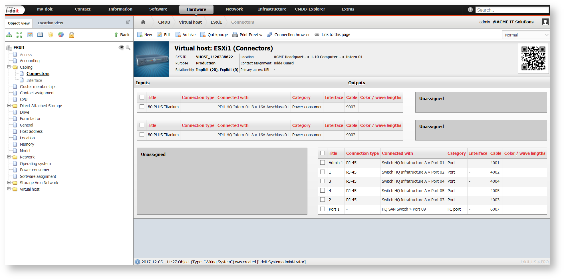
If the selected object has a physical connector of any kind, it can be documented in the Connectors category.
Every connection is defined either as an Input or as an Output. You can establish an n-to-n relation between inputs and outputs:
- Connection between an input and an output
- Connection between an input and several outputs
This connection between input and output is optional and makes only sense under certain conditions. An example is a patch panel with the possibility for placing cables which lead into ports. This is the origin of a 1-to-1 relation between input and output.
The Connectors category is automatically filled with entries by other categories:
- Network → Port: If a new port is created, it is automatically defined as a new output.
- Power consumer: If a new power supply is created, its power connection is automatically defined as a new input.
- Cabling → Interface: If a new interface is created, it is automatically defined as a new output.
- Storage Area Network → FC Port: If a new fiber channel port is created, it is automatically defined as a new output.
Category for Interface#
The Interface category is for the creation of further connections which do not concern the wiring for the network or power cabling. This could be connections of peripheral devices, such as monitors via HDMI or printers via USB.
Object Type Cable#
The Cable object type contains all objects which represent a cable. In i-doit it is mandatory that a cable has a beginning and an end. Y cables or similar cables are not supported. Here, the user has content himself with an auxiliary object at Cabling → Connectors that contains an input with two outputs which are connected to each other (1-to-2 relation).
The characteristics of a cable are defined in several categories which are explained as follows.

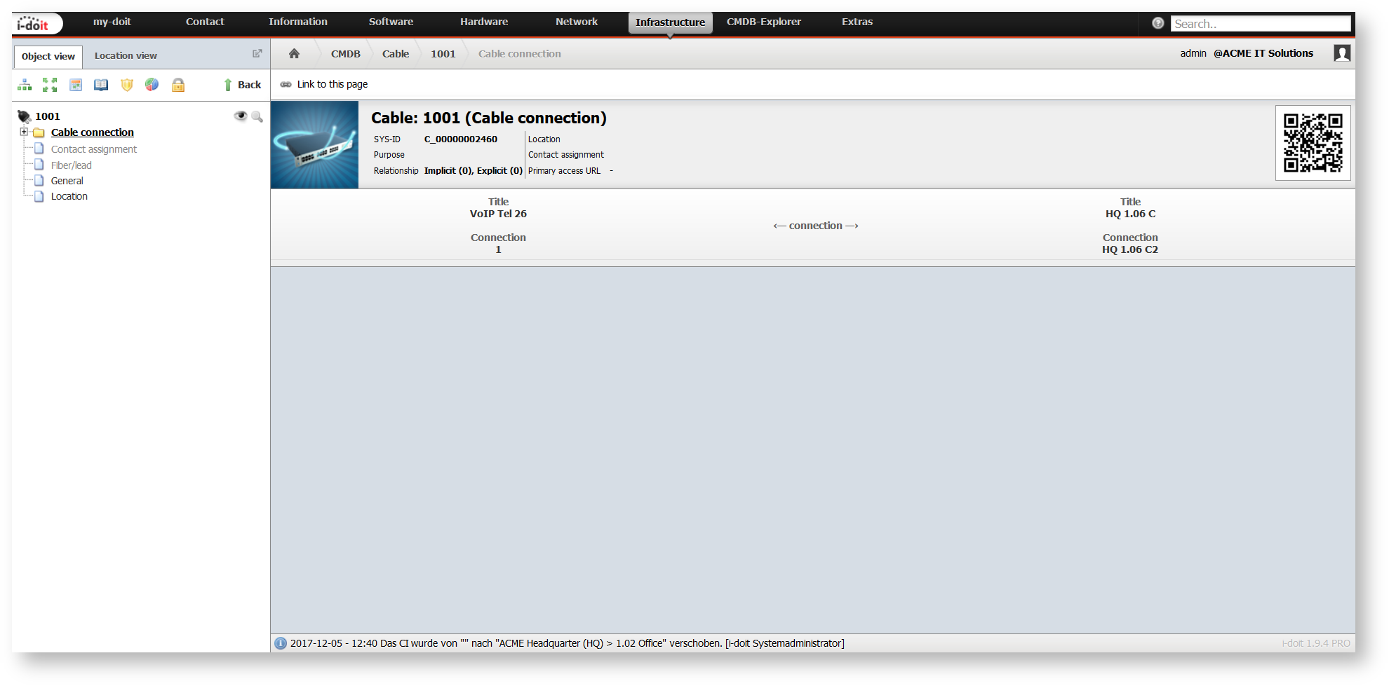
Category Folder for Cable Connection#
The category folder for the Cable connection contains the Cable category and is therefore typically assigned to the Cable object type. The folder shows to which device the cable is connected.
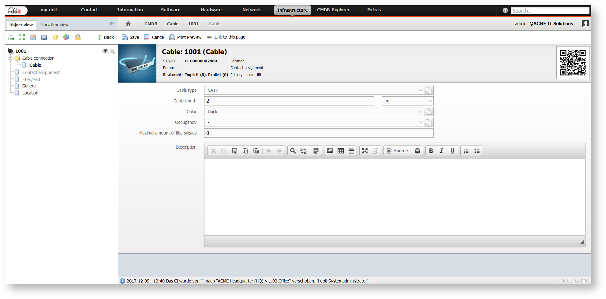
Category for Cable#
The essential properties of a cable are recorded in the category Cable connection → Cable:
| Attribute | Description |
|---|---|
| Cable type | Specification of the cable, for example, "CAT7" or "LWL" |
| Cable length | Length of the cable – not only in centimeters |
| Color | Color of the outer sheath |
| Occupancy | How many fibers/ leads does the cable contain? |
| Maximal amount of fibers/leads | How many fibers/ leads are to be used as a maximum? |
Category for Fiber/Lead#
If you want to/ have to document even the smallest detail, you will love the Fiber/Lead category. You can specify further properties for each fiber of a fiber optic cable or for each lead of a copper cable:
| ### Attribute | ### Description |
|---|---|
| Label | Description |
| Category | Relevant for LWL (OM1-4, OS1-2) |
| Color | Wavelength |
| Damping | in dB |
| RX | Connection to receive data |
| TX | Connection to send data |

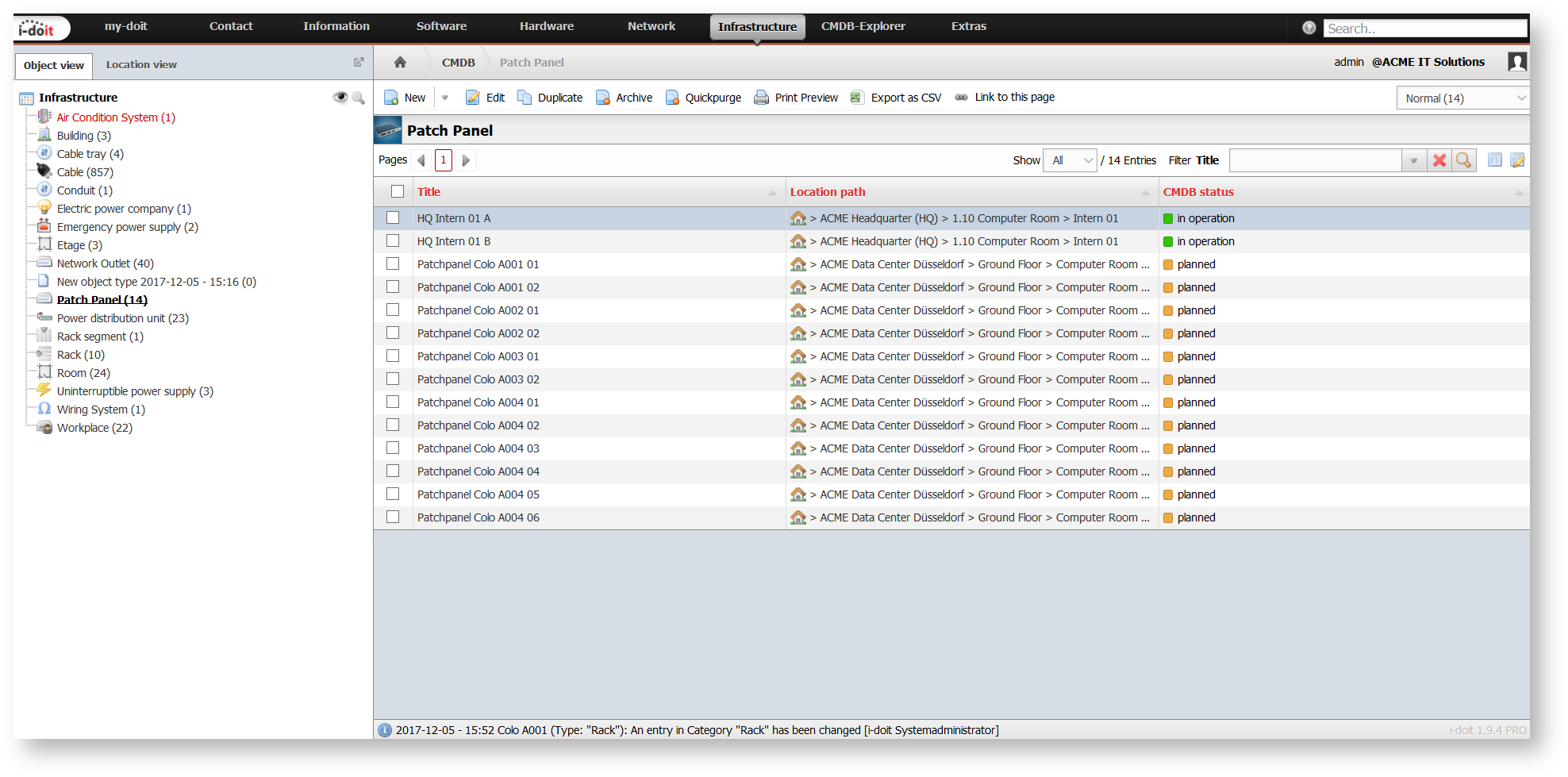
Object Type Patch Panel#
Patch panels are documented in i-doit as objects of the type Patch Panel. Typically, the category folder Cabling is assigned to this passive component. In the category Cabling → Connectors you can define the ports: An Input represents the network port; an Output represents the cable. Input and output are connected with each other.
The Connection browser (see below) is helpful if you require a quick connection of patch panels.
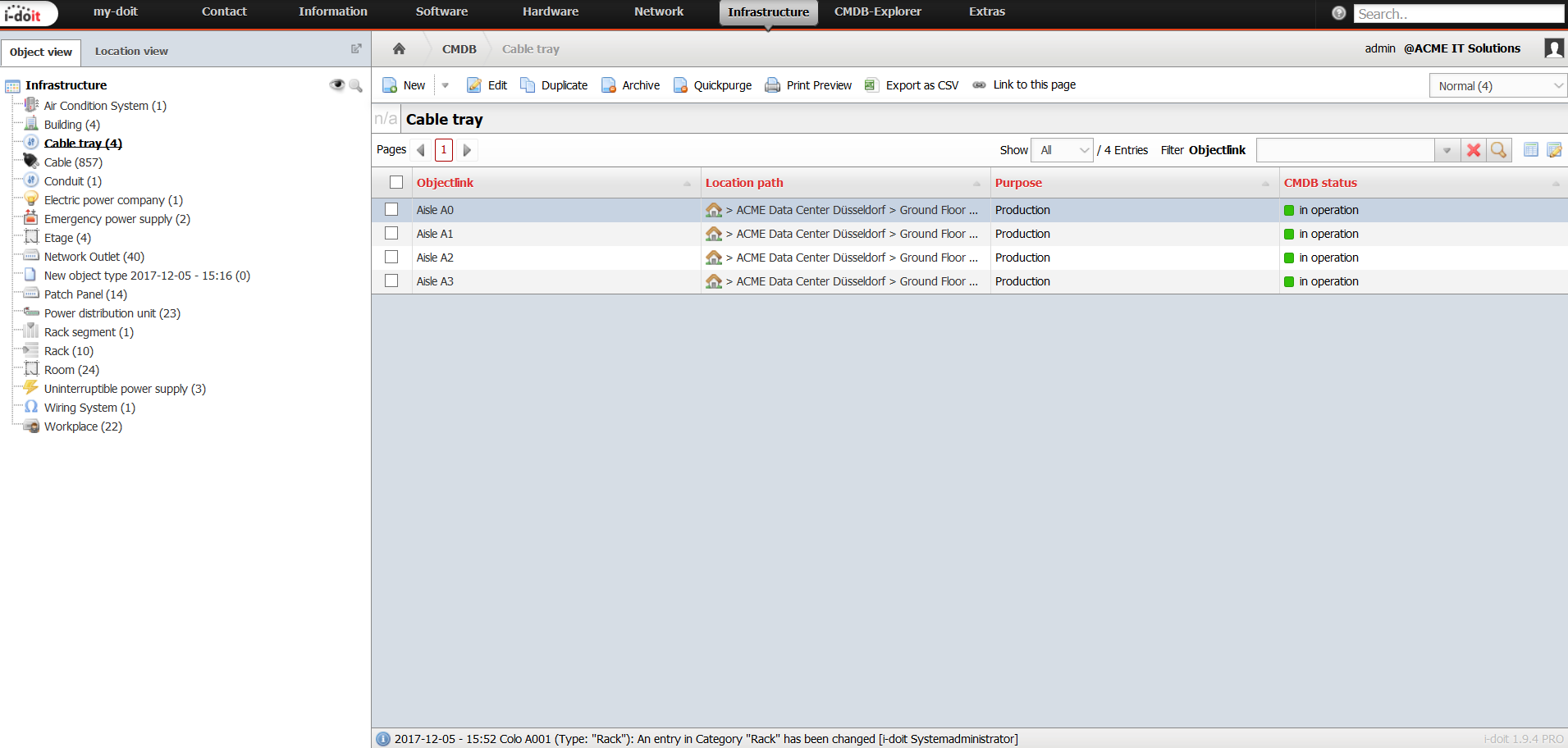
Object Type Cable Tray#
Cable trays are a standard in server rooms and computer centres. They bundle up several cables and provide for ordered ways. Hence, the object type Cable Tray contains the categories Location and locally assigned objects to take up cables. In turn, objects of the type Cable are assigned to the Location category.
Object Type Conduit#
Along the same lines as the Cable Tray object type (see above) is the Conduitobject type.
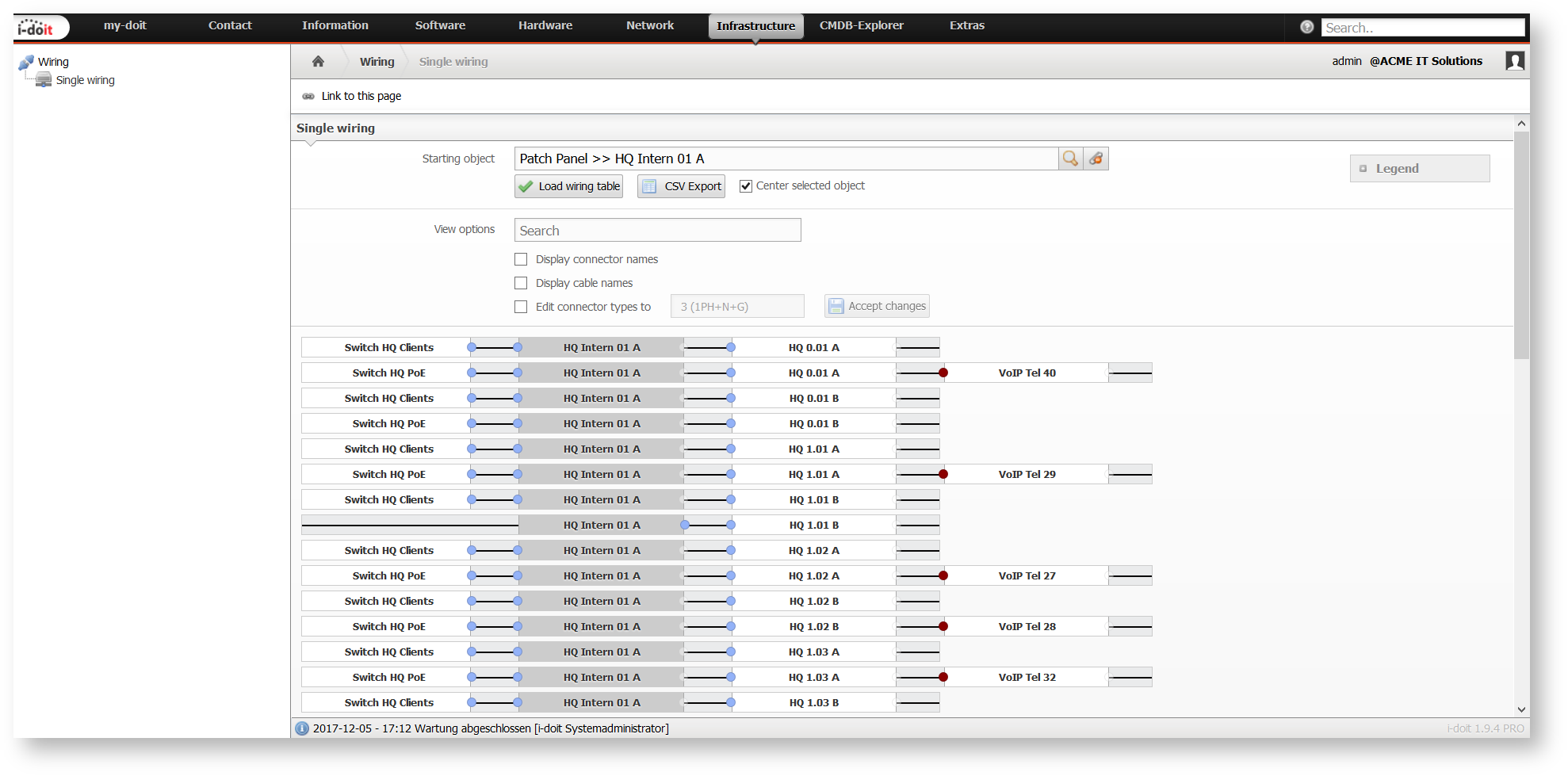
Single Wiring#
The category folder for Cabling already contains several visualization options. Additionally, there is another view under Extras → CMDB → Wiring → Single wirings with further functions. After selecting a cabled object, all incoming and outgoing cable routes are displayed. In addition, names of the connections and the cables can be displayed or hidden. By means of filtering you can display only selected routes.
With check boxes you can change the type of several connections simultaneously.
The cable routes can be exported in CSV format.
Connection Browser#
This function enables an easier quick connection of two objects. This item can be found under the category Cabling → Connectors via the Connection browser button. A precondition is the existence of already documented connections of both objects.

The opened Connection browser offers a two-part view: The object which was selected by the user is indicated on the left side with all available connections. Inputs and outputs are displayed separately. A second object is loaded with all its connections on the right side, so that both objects can be connected with each other.
You can link the connections of the first object displayed on the right to the connections of the second object displayed on the left. The view of the inputs and outputs can be mirrored, so that you can show inputs as well as outputs either on the left or on the right side.
With the button Load next object you can trace the existing connection routes of an object.
Select the connector check boxes to connect the connectors between both objects. With the top checkbox you choose all available connectors. You can select a range of connectors by using the Shift key. It is important that the number of connectors of the first object corresponds to the number of connectors of the second object.
With the corresponding button (Connect connectors) you connect the selected connectors of both objects with each other. The logical approach is to connect the selected connections from top to botton, one after the other, until you reach the end of the list.
For every new connection i-doit plans a Cable object. With the checkbox Automatic cabling new Cable objects are created without further questions. Otherwise, you have to select an existing Cable object for every connection in a new window.
With the button Change selected cable you can choose an alternative cable object for the selected connections.
The button Disconnect connectors effects that the connections of the selected connectors are deleted irrevocably.

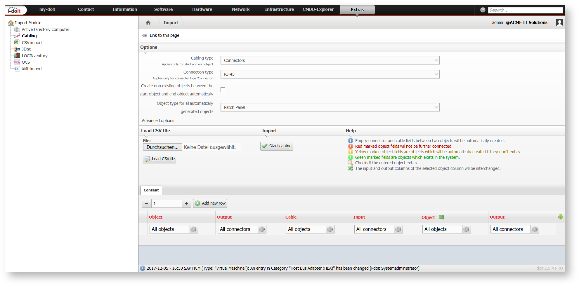
Cabling Import#
You can create cabling routes in i-doit via the import of a file in CSV format. The required steps can be found at Extras → CMDB → Import → Cabling.
The following options are available:
| Option | Description |
|---|---|
| Cabling type | In which category do you want to create entries? You can choose between: Connectors* (see category Cabling → Connectors) FC Ports (see category Storage Area Network → FC Port) Ports (see category Network → Port) * Interface (see category Cabling → Interface) The category is considered only with the first and with the last object of the respective cabling route. With all other objects in between the entries are imported in the category Cabling → Connectors**. |
| Connection type | Which connection is involved? You can select all entries of the Connection type attribute in the Cabling → Connectors category. The list can be adapted at Administration → CMDB settings → Dialog Admin → Connectors: Connection type. |
| Create non existing objects between the start object and end object automatically | If this option is activated, you can create non-existing documented objects between start object and end object automatically during import. |
| Object type for all automatically generated objects | If the above mentioned option is active, you have to define additionally to which object type the newly created objects shall be assigned. |
With the Load CSV file button you can load a selected file and analyse it. The result can be found in the Content tab.
The lines and columns of the CSV file are displayed in the Content tab. You can define new lines and columns with the respective buttons. Every line represents a cabling route with a start object and end object as well as any number of objects in between.
The start object consists of an object title and an output, the end object of an object title and an input. The objects in between each have an input and an output. Between the connectors are objects of the type Cable and they also receive an object title. The inputs and outputs of the objects in between can be exchanged subsequently. When the connectors and cables do not receive names, they will be numbered consecutively.
The assignment of the object titles and connectors is carried out either with the CSV file or with the text fields. An automatic name assignment for every column individually is possible.
Also usable without CSV file
You do not necessarily need a CSV file for the import. Instead, you can use the Content tab to create cable routes manually.
Non-existing objects are displayed in red, objects to be created automatically are shown in yellow and already existing objects are highlighted in green. These are identified with the help of the object title and object type.
You can import the cabling routes with the Start cabling button.