Cable Patches and Pathways#
In this article you will learn how to cable hardware objects in i-doit -- from Ethernet and fiber optics to power supply.
Concept#
i-doit strictly separates the documentation of connections from the physical cabling:
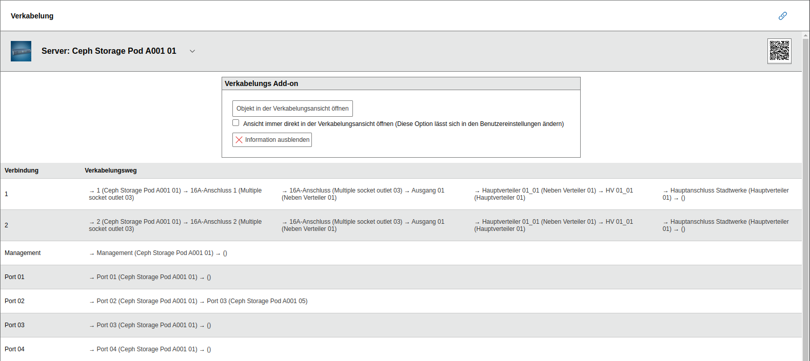
- Connections between active components: In the category Network > Port, you record which server is connected to which switch. Connection paths across multiple components become visible.
- Passive components: Patch panels and patch outlets can optionally be documented. If the connection between active components is sufficient, you can leave out passive components and cables.
i-doit documents the cabling in the background without requiring additional steps from you. If you need more detail later, you can extend the existing documentation -- you do not need to start over.
In addition to forms, functions for visualization, reporting, and importing are available.
Category Folder Cabling#
Every object type can be configured with the Cabling category folder. This gives objects of these selected types the categories Connectors and Interface.
The category folder is suitable for all objects that contribute an active or passive part to the cabling.
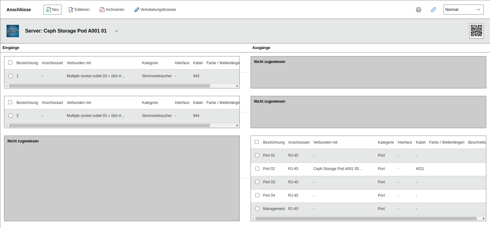
Category Connectors#
If the selected object has a physical connector of any kind, it can be documented in the Connectors category.
Each connector is defined as either an input or an output.
- Connection between an input and an output
This connection between input and output is optionally and only meaningful under certain conditions. For example, a patch panel has the ability to terminate cables that end in ports. This creates a relationship between input and output.
The Connectors category is automatically populated with entries by other categories:
- Network > Port: When a new port is created, it is automatically defined as a new output.
- Power consumer: When a new power supply is created, its power connector is automatically defined as a new input.
- Cabling > Interface: When a new interface is created, it is automatically defined as a new output.
- Storage Networks > FC Port: When a new Fiber Channel port is created, it is automatically defined as a new output.
Category Interface#
The Interface category is used for creating additional connections that do not involve network or power cabling. These could be connections to peripheral devices such as monitors via HDMI or printers via USB.
Object Type Cable#
The Cable object type contains all objects that represent a cable. In i-doit, a cable necessarily consists of a beginning and an end. Y-cables or similar are not supported. In this case, you must use a helper object that contains one input with two outputs connected to each other under Cabling > Connectors (1-to-2 relationship).
The properties of a cable are defined in several categories, which are explained below.

Category Folder Cable Connection#
The Cable Connection category folder contains the Cable category and is therefore typically assigned to the Cable object type. The folder itself shows what the cable is connected to.
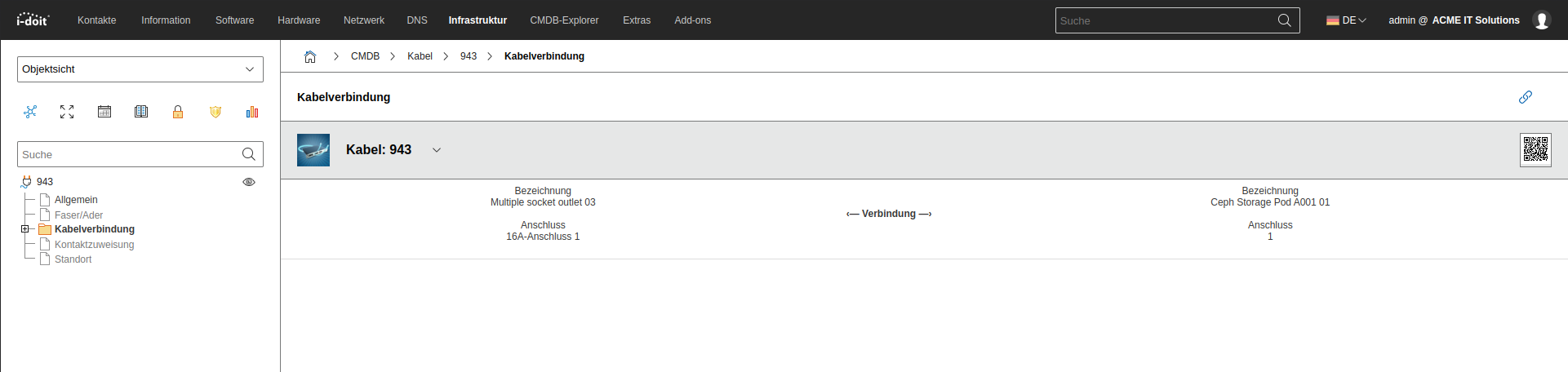
Category Cable#
The essential properties of a cable are recorded in the Cable Connection > Cable category:
| Attribute | Description |
|---|---|
| Cable type | Cable specification, e.g., "CAT7" or "Fiber" |
| Length in CM | Length of the cable -- not only in centimeters |
| Color | Color of the outer sheath |
| Occupancy | How many strands/fibers does the cable contain? |
| Maximum number of fibers/strands | How many strands/fibers may be used at most? |
Category Fiber/Strand#
Those who want or need to document down to the smallest detail will appreciate the Fiber/Strand category. For each fiber of a fiber optic cable or each strand of a copper cable, additional properties can be stored:
| ### Attribute | ### Description |
|---|---|
| Label | Designation |
| Category | Relevant for fiber (OM1-4, OS1-2) |
| Color | Wavelength |
| Attenuation | in dB |
| RX | Line for receiving data |
| TX | Line for sending data |
Object Type Patch Panel#
Patch panels are documented in i-doit as objects of type Patch Panel. This passive component is typically assigned the Cabling category folder. In the Cabling > Connectors category, the ports are defined: An input represents the network port. An output represents the terminated cable. Input and output are connected to each other.
For quickly connecting patch panels, the cabling browser is suitable.
Cabling Browser#
This function makes it easy to quickly connect two objects to each other. It can be accessed in the Cabling > Connectors category via the Cabling Browser button. Already documented connectors on both objects are required.
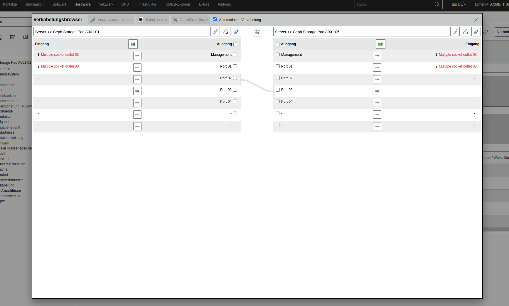
The opened Cabling Browser provides a split view: The object the user is currently in is displayed with all available connectors on the left side. Inputs are displayed separately from outputs. On the right side, a second object is loaded with its connectors so that both objects can be connected to each other.
The outputs shown on the right of the first object and the inputs shown on the left of the second object can be connected to each other. The view of inputs and outputs can be mirrored so that both inputs and outputs are displayed on the left or right respectively.
The Load Next Object button follows an existing cabling path.
To connect one connector each between the two objects, the checkboxes of the connectors are selected. The topmost checkbox selects all available connectors. A range of connectors can be selected with the Shift key. It is important that the number of connectors of the first object matches the number of connectors of the second object.
The Connect Connectors button connects the selected connectors of both objects. The logic provides for connecting the next selected connectors from top to bottom until the end of the list is reached.
i-doit provides a Cable object for each newly connected connector. With the Automatic Cabling checkbox, new Cable objects are created without confirmation. Otherwise, an existing Cable object must be selected in a new window for each connection.
The Change Cable button allows selecting an alternative cable object for the selected connectors.
The Disconnect Connectors button irrevocably deletes the connection of the selected connectors.
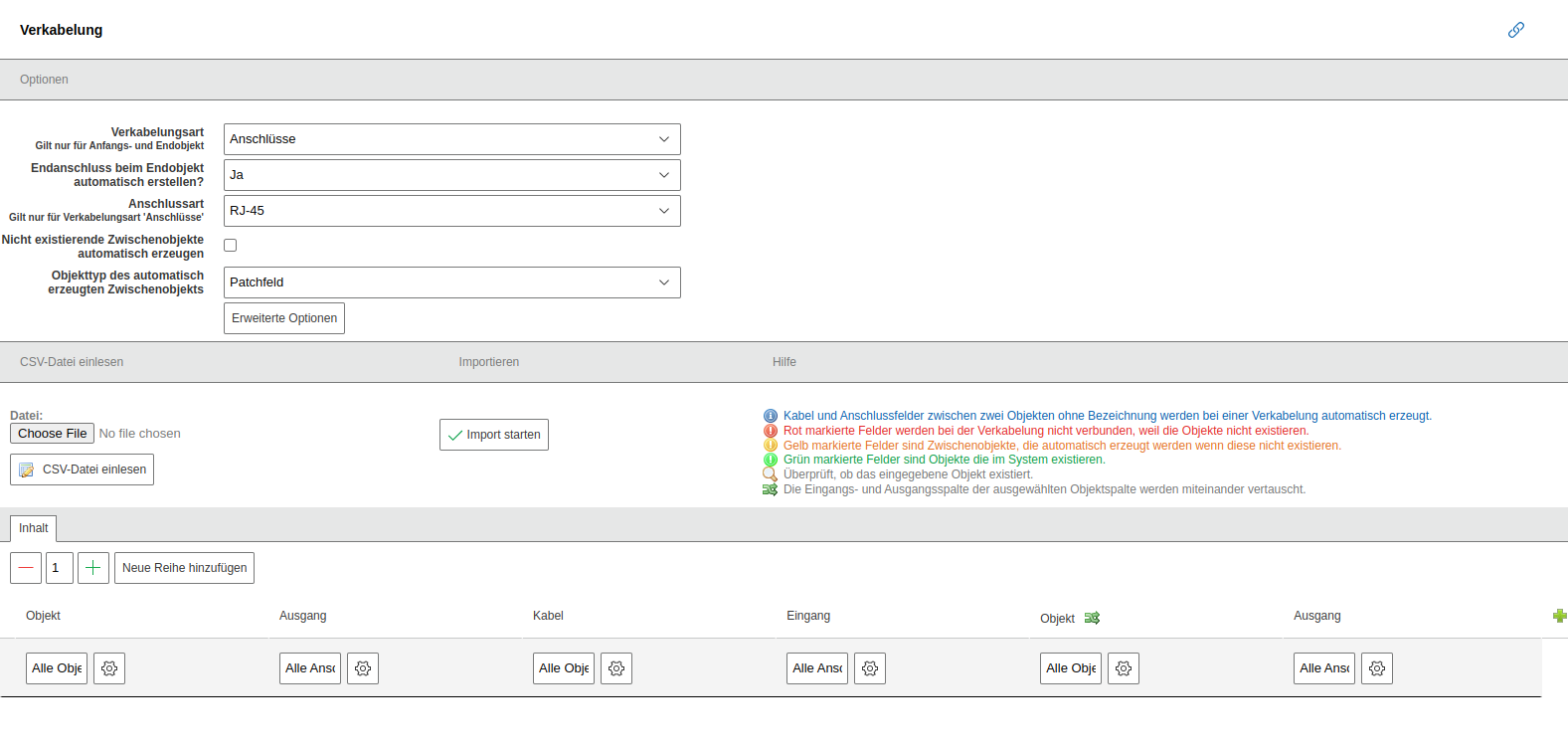
Cabling Import#
Cabling paths can be created in i-doit by importing a file in CSV format. The necessary steps can be found under Extras > CMDB > Import > Cabling.
The following options are available:
| Option | Description |
|---|---|
| Cabling type | In which category should entries be created? Options include: - Connectors (see category Cabling > Connectors) - FC Ports (see category Storage Networks > FC Port) - Ports (see category Network > Port) - Interface (see category Cabling > Interface) The category is only considered for the first and last object of the respective cabling path. For all other intermediate objects, entries are imported in the Cabling > Connectors category. |
| Connector type | What type of connector is it? Options include all entries of the Connector type attribute in the Cabling > Connectors category. This list can be customized under Administration > Predefined Content > Dialog Admin > Connectors: Connector type. |
| Automatically create non-existing intermediate objects | When this option is enabled, objects that are not yet documented between the start and end objects can be created during import. |
| Object type of the automatically created intermediate object | When the above option is active, it must additionally be defined which object type newly created objects should be assigned to. |
The Read CSV File button uploads and analyzes a previously selected file. The result is found in the Content tab.
Within the Content tab, the rows and columns of the CSV file are displayed. New rows and columns can be defined via the corresponding buttons. Each row represents a cabling path with one start and one end object as well as any number of intermediate objects.
The start object consists of an object title and an output. The end object consists of an object title and an input. The intermediate objects have one input and one output each. Between the connectors are objects of type Cable. An object title is also assigned for these. For intermediate objects, input and output can be swapped subsequently. If no names are assigned for the connectors and cables, they are numbered sequentially.
The assignment of object titles and connectors is done either via the CSV file or via the text fields. Automatic name assignment is possible individually for each column.
Also usable without a CSV file
A CSV file does not necessarily need to be provided for the import. Instead, the Content tab can be used to manually create cabling paths.
Non-existing objects are marked in red, objects to be automatically created in yellow, and already existing objects in green. They are identified based on the object title and type.
The Start Import button imports the cabling paths.